I designed and built a quadruped robot dog from scratch this summer for a “Mech Warfare” airsoft battlebots competition. I’ve always wanted to build something with legs, and this seemed like a great opportunity to push the boundaries on my mechanical design skills. This blog covers my design process, stress testing, and final robot that I built :)
The competition
The rules of Mech Warefare are pretty simple:
- No wheels, legs only (for the vibes)
- Airsoft guns and target pressure plates for scoring
- You can’t see the robots during the competition. It all has to be FPV video streaming
- “No gimmicks” (learning of this rule immediately threw out most of my ideas)
After watching some videos of past competitions, I decided that my strategy would be to maximize speed so I could attack opponents from the side and back before they realized what was happening. (I also have future ambitions to build an auto-aim stable enough to fire while moving, but haven’t gotten to that yet).
Quadruped Design - Background research
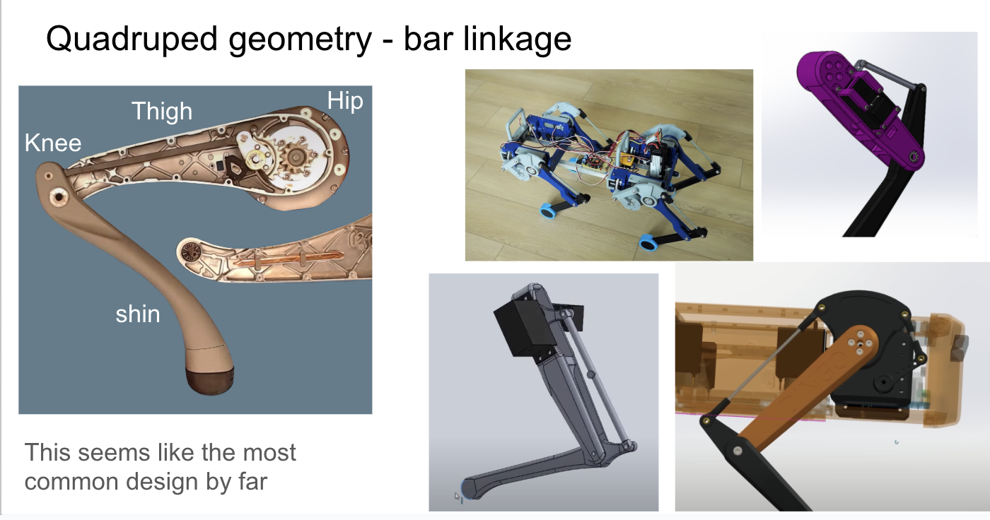
Most contestants use older “spider” like designs, but for speed I wanted to use a more dynamic dog like design, similar to Boston Dynamic’s Spot and the Unitree Stellar Hunter. I started exploring the web for every example of robot leg geometry and known best practices that I could find.
.png)
The most common two designs I found were 1) 4-bar-linkages, and 2) parallel linkages. Both of these really just boil down to how to use two motors to place the “foot” at an arbitrary X,Y location.
Now wouldn’t it be simpler to just have one motor at the hip, and one motor at the knee?
That works, but motors are heavy, and moving one around at the knee creates a LOT of extra work for the hip motor. It’s much better to keep the motors as stationary as possible, and use a mechanical linkage to transfer the motion to the knee. I decided on the 4 bar linkage, as the simpler design (and because it’s what Unitree uses!)
Robot Math
For the next step in my design, I would need Forward Kinematics (FK) and Inverse Kinematics (IK). These are the equations that let you convert between foot X,Y coordinates, and motor angles (theta1, theta2) between each other.
Forward Kinematics is how you take motor angles and calculate where the foot (“end effector”) will be. It is quite simple for this design:
\[\begin{bmatrix} x \\ y \end{bmatrix} = L_{thigh} \begin{bmatrix} \cos\theta_{thigh} \\ \sin\theta_{thigh} \end{bmatrix} + L_{shin} \begin{bmatrix} \cos\theta_{knee} \\ \sin\theta_{knee} \end{bmatrix}\]Note that the two thetas are fully independent of each other, because with a 4 bar linkage design, rotating the thigh does NOT rotate the shin!
Inverse Kinematics is the opposite - given a foot X,Y location, what motor angles will get you there? For complex robots this can be super hard - either requiring a rats nest of trigonometry, or just solving it numerically with an optimizer. Luckily our case is fairly simple!
We can use the law of cosines which relates the angles and side lengths of any triangle to find the knee angle:
\[c^2 = a^2 + b^2 - 2ab\cos C\]Where c is the distance from foot to hip, a is our thigh length, and b is our shin length, and C is the knee angle. c^2 will be x^2 + y^2 by the pythagorean theorem.
# Use law of cosines to find theta2
cos_theta2 = (x**2 + y**2 - len1**2 - len2**2) / (2 * len1 * len2)

# Two possible solutions for theta2 (knee forward and knee backward)
theta2_knee_forward = np.arccos(cos_theta2)
theta2_knee_backward = -theta2_knee_forward
theta2 = theta2_knee_backward

# k1 and k2 are the x and y components of the target point (FootX, FootY)
# as seen in a coordinate frame that rotates with the first link.
k1 = len1 + len2 * np.cos(theta2)
k2 = len2 * np.sin(theta2)
theta1 = np.arctan2(y, x) - np.arctan2(k2, k1)
Honestly, Claude just one-shotted this for me and when I visualized the results, they looked correct. As a side note, I’m a big believer in Vibe Coding as long as you have a way to verify the output. In my case it was much easier to verify correctness by playing with this interactively than by staring at the code.
Hyper Parameters
Next, I had to decide the size and shape of my legs - how long should the thigh be, how long should the shin be? How high should It walk above the ground, and how long should each step be? The optimal leg design would be tied to my Gait design, so I wanted to answer all these questions at once.
I decided to approach this like any ML Researcher would - a hyper parameter scan! With my IK code, I can take any leg geometry and any gait parameters (stride length, stride height, period) and calculate the necessary motor angles as well as all the speeds, accelerations, and torques needed to support a particular weight!
I did a parameter sweep of 8000 leg and gait configurations and plotted various characteristics like max torque and max velocity that it would require from the motors (all configurations constrainted to go at a speed of 1m/s).
This was a really valuable exercise to build design intuition and how all these variables related to each other. I didn’t have a single objective function to optimize, so I ended up picking a design that was a balance between optimizing torque and speed: a 16cm thigh and shin.
Motors
.png)
I was already planning to use Dynamixel MX-106Rs that I had from a previous project, and by my calculations my 16cm leg design was well within their torque and speed limits:
Stall Torque: 8 Nm
Speed: 41 rpm
As a side note, Dynamixels are pricy so I wouldn’t recommend them for most hobbiests. They’re very high quality, and a lesson that I’ve learned over and over again is that it’s worth it in the long run to pay for nice hardware to save yourself time. Time is the biggest limiting factor for my side projects, so this tradeoff was worth it for me. My quick pitch of what the extra $$$ gets you over hobby servos:
- Repeatability. Every dynamixel servo will behave exactly the same. With cheap hobby servos I’ve frequently found that each one behaves a little differently and that wreaks havoc on my code.
- Feedback. They report their position with 4096 clicks per rotation resolution, and how much torque / current they’re using. They’ll tell you if they exceed max torque or under-voltage etc.
- Full programmability. You can set the PID constants in the servo, set torque and position limits, change from “servo direction” mode to “continuous rotation wheel” mode etc, and all that runs directly on the servo. Loading position limits into the servo has saved my hardware from shitty code many many times!
- Daisy Chaining. They speak RS-485, and you can daisy chain them together to reduce wiring.
First Leg Design
.png)
The two servos face each other, one directly driving the thigh, and the other driving a bar linkage that controls the shin. To connect each bar there are simple M3 screws through them, with a nylon washer between to reduce friction.
.png)
The leg segments are 3D printed PLA. I have never experimented with more advanced filaments, but some of my friends who have told me that any strength benefit wasn’t worth the added difficulty of printing.
Initial motion tests went well, and I could run my gait calculation code to drive the leg through a walking motion.
Doing a walking motion in air was one thing, but I needed to find out how my design would actually hold up carrying a heavy robot, slamming into hard ground, etc. Some of the things I was worried about were the front bar linkage breaking, or the servo mounting block breaking. That block was the center of all torque in the leg between both servos! Time to do some stress testing!
Stress Testing
To save time building a testing rig, I decided to test the leg upside down, with a weight hanging from it. Instead of the leg lifting itself up as it stepped, it would just lift a weight and the “hip” would remain stationary, clamped to the table.
I ran this for about ~1hr with a 4lb weight (1/2 of my projected robot weight) and at 1/2 of my target walking speed. The “1/2 robot weight” is because in a trot, there are always two legs on the ground. The “1/2 target walking speed” is because when running any faster this thing made a huge racket slamming the weight down on the ground and I didn’t want my upstairs neighbors to get mad at me 🤣.
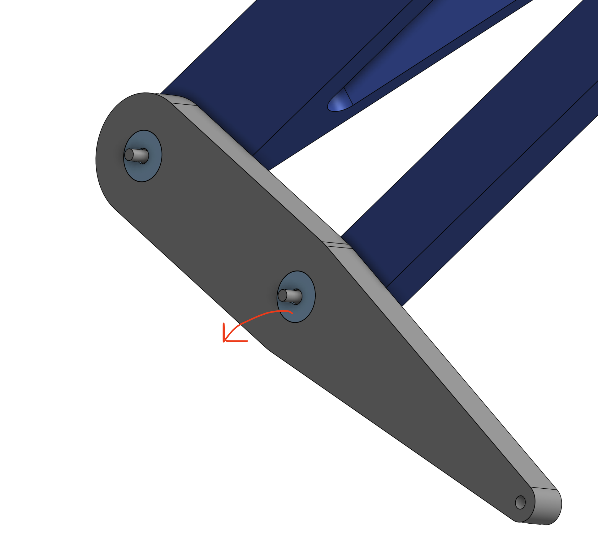
Next up was a side load test: How does the leg handle sideways forces that will occur when turning or straifing?
This looked MUCH worse! There’s a huge amount of bend in the bars and the leg is tilting practically 20 degrees to the side! Defintely will need to strengthen the leg for side to side forces.
After all the stres testing was done, I took everything apart to look for damage and problems:
- The screws were wearing holes through the legs, adding a lot of slop to the joints
- There was some umm, thigh chafing…
.png)
Legs++
My two big goals for my updated leg design were
- Much stronger side-to-side strength
- Replace the through-hole screws with actual bearings, so they wouldn’t carve through the plastic as they rotated.
.png)
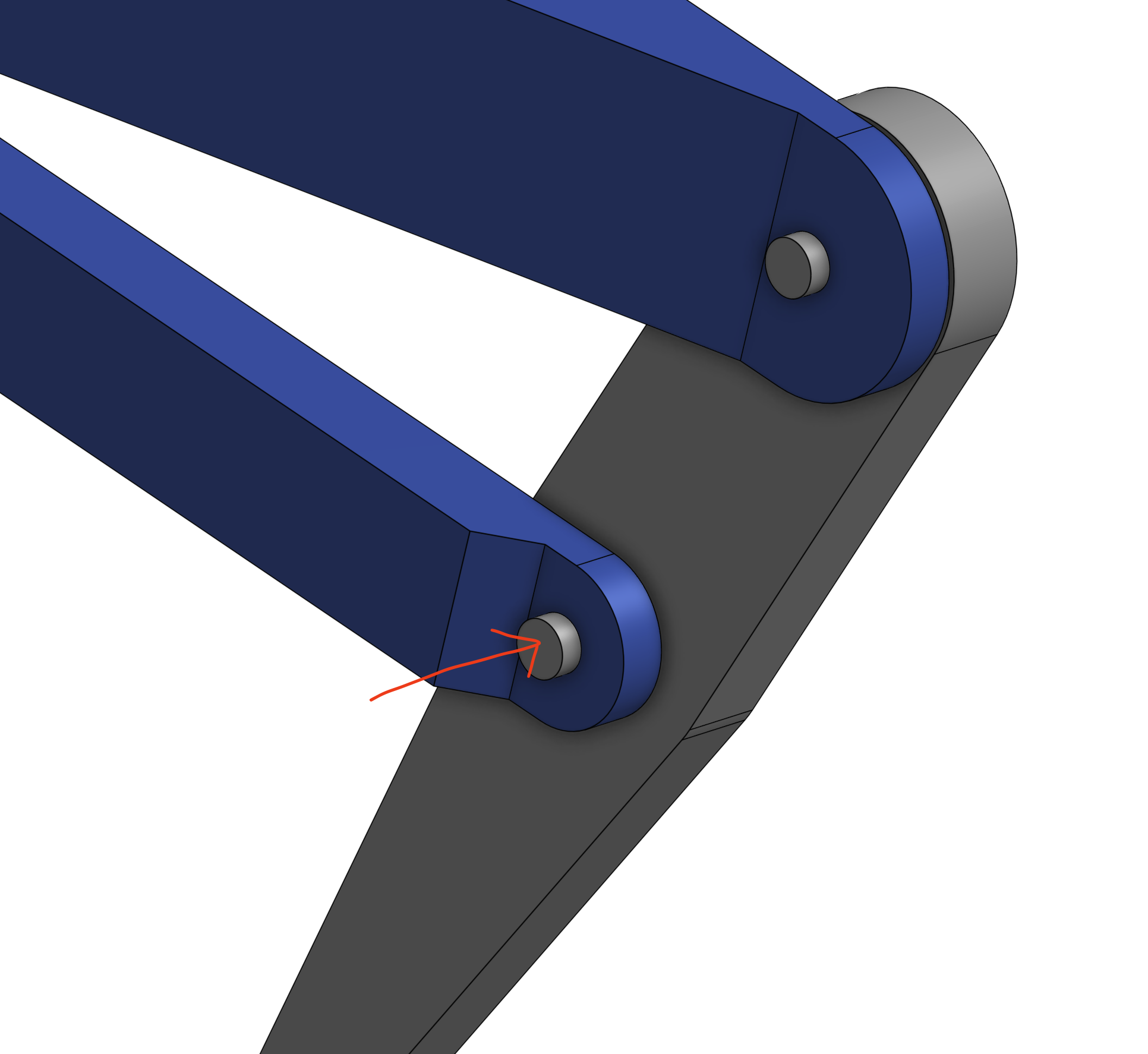
The primary change was making the thigh attach to both sides of the servo to form a strong triangle against side to side motion. (Dynamixels conveniently have a mounting hole exactly opposite their horn).
.png)
I beefed up the thickness of all the leg bars from 5cm to to 10cm, and replaced the through-hole M3 with a 4mm Shoulder bolt going through two 4x13x5mm bearings that are press fit into the leg. I used shoulder bolts instead of M4 screws, because screws are always slightly smaller than their nominal value, and would rattle around inside the bearing. Should bolts are much tighter tolerance and have a smooth, snug fit.
.png)
Designing the rest of the robot
Up until this point, I’d been living in a 2D world, but it was time to venture out into the 3rd dimension. I would need a way to tilt the legs side to side (to straif and to rotate the robot), and I needed to plan how all 4 of these legs would actually mount into the overall robot.
.png)
I designed a pivot point through the servo mounting block that would be driven by a 1:3 gear reduction to another servo mounted above the leg. I used the gears in part because there was no easy way to mount the hip abduction (side to side motion) servo directly to the block, and also so that I could use a cheaper, lower torque dynamixel servo.
.png)
The servo block gets yet another high torque connection to it.
.png)
The body itself would be 4 carbon fiber tubes with flat plates clamped onto them. The legs would mount onto these plates, each of which was very easy to 3d print because it was flat with no overhangs.
I had never worked with carbon fiber before, but I was incredibly impressed at how rigid they were. Once I tightened all the plate clamps, I could not get the chassis to twist or flex AT ALL, even trying as hard as I could. The tubes were 25mm outer diameter, 420mm long, and each one was about $12 on Amazon. I will definitely design more projects using CF tubes!
My plan was for the rest of my electronics and other parts to clamp onto on the tubes at any location, giving me a ton of flexibility.
Software to walk in 3D
Luckily extending my FK and IK into 3D was quite easy. The axis of side to side rotation was directly inline with the “2D” leg, so all I Claude had to do was rotate a plane to the side, and then solve 2D kinematics in that plane.
# First, determine the abduction angle
# The leg must lie in a plane containing the X axis
# This plane is determined by the Y and Z coordinates
yz_dist = np.sqrt(y**2 + z**2)

# Calculate abduction angle
theta_abd = np.arctan2(z, -y)
y_in_plane = y * np.cos(theta_abd) - z * np.sin(theta_abd)

# Adjust target for hip offset (hip is at y_local = -hip_offset in plane)
x_target_in_plane = x
y_target_in_plane = y_in_plane + hip_offset

# Now solve 2D IK in the rotated plane
solutions_2d = ik_2d(x_target_in_plane, y_target_in_plane, len1, len2,
                        theta2_relative=theta_knee_relative, only_one=only_one)
I also adjusted the gait generation code to take in a heading and generate foot paths for side-to-side straifing.
From One leg to Four
Next, I needed to coordinate the motion of all 4 legs. I’m using a Trot which is a simple gait where the diagonal legs always step together, and the pairs are 180 degrees out of phase. For any translation, I just need to calculate a single gait, and then apply it to all 4 legs, but with different time offsets.
For rotation, each foot will move in the direction tangent to the circle of rotation.
_(1).png)
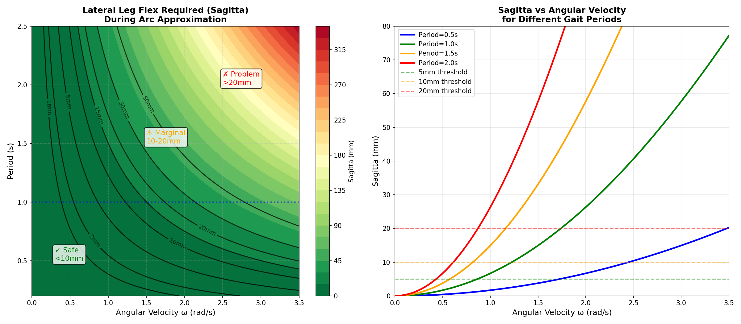
Technically, I should make the foot trace an arc during this rotation, rather than a straight line, but Claude and I did some math and came to the conclusion that this approximation would be fine. The maximum distance between an arc and the straight line approximation I’m using is called a “Sagitta”. This is the distance that my leg will need to bend to make up for the difference.
.png)
As long as the steps are short and quick this distance will be less than 1cm.
Now to combine linear motion and angular rotation of the robot, for each foot I can just take a linear combination of velocity from the two motions.
_(1).png)
And with that, I had a robot that could move around in all directions!
A quick note on stability: I’m not doing any “active” balancing, I’m just running the leg gaits open loop. This works well at high frequency gaits (0.25s period) because the body has enough rotational inertia to not go too far out of balance between steps. If I slow down the gait period to 0.5s or above, the robot tips over between steps.
One of my longer term ambitions is to train an RL algorithm to control the motion, so I’m not going to invest too much more in the classical controls of the gait.
Now for the fun part… the airsoft turret!
I’ve never played airsoft before, but the guns work by having a motor pull back a powerful spring, which is released and then drives a piston to shoot high velocity air out behind the plastic BB. This thing is a cannon! (Sound on for extra fun)
The turret has two dynamixel servos to pan and tilt, a hopper to hold BBs, and the CSI camera mounted just over the barrell to aim down the sights.
.png)
Ammo Hopper
Somewhat surprisingly, the hardest part of this design was the Hopper, which would always jam after a few shots as the BBs formed stable arches over the exit hole. Apparently this is a big known problem called Bridging that mechanical engineers working on things like grain silos have to deal with, and the solution is either to make the hole much bigger (doesn’t work for me, because I need to get a single BB at a time into the firing chamber), or add a motor to stir or move the BBs.
.png)
Most other Mech Warfare teams use an extra motor to control their hoppers, but I was running out of time before the competition, and didn’t have time to do anything more than a simple cone shaped hopper. When my gun jammed during the competition I had to take a few steps with the robot to shake the BBs loose!
Part of me still thinks there’s some clever, weird, asymmetric geometry that will passively never get stuck, but I couldn’t figure anything out.
Auto Aim
The target plates for the competition each have an IR LED on them for auto-aim systems. Using a zoomed in CSI camera with no IR filter, I can track the target by just finding the most red pixel. The video looks pink because without an IR filter, there’s more light coming into the red channel pixels than a normal camera.
I calibrated which pixels the BBs actually go towards [red], and then use a PID controller to drive the tracked target [green] to the desired spot.
I feel like I should be able to improve the tracking and performance of this a lot, but I think the limiting factor is the latency of my tracking.
(And yes, I was wearing safety glasses for all this testing)
Systems
The core of the robot is a Raspberry Pi 3b+. (In retrospect, I should have used a Pi 5 for the extra compute, but at the time I was worried about power consumption and battery life)
_(1).png)
With a laptop on the same wifi network as the Pi I can stream video over WebRTC and pass telemetry / commands via a websocket connection, all from a web app control interface.
All my code ran on the Pi as a systemd service launching a main python server. This server launched a few threads which:
- Handled webrtc commands, and save desired velocity into a variable behind a lock.
- Translated desired velocity into gaits and motor positions, then sent motor commands to the dynamixels
- Ran the computer vision tracking code
- Launched the video streaming MediaMTX server
Control Interface
Building the control interface and UX for this competition was surprisingly fun! I’m not much of a frontend person, but I do appreciate great UX. Some key elements:
- Maximize camera real estate
- Hotkeys for everything (stand up / sit down / toggle auto aim)
- The turret camera was so zoomed in, it was hard to feel which direction it was pointing. I added a 3d rendered green arrow that always points towards the robot body’s front, so I can feel this without looking away from the turret cam.
- It could be confusing whether auto-aim was enabled or not, so the turret cam highlights in green when it’s active.
- I added 3 additional keys around IJKL (H, 8, ;) to snap the turret to 90 degrees left, straight ahead, 90 degrees right, respectively. These were really handy when passing an opening to the side and quickly looking down it, then back forward.
- WASD+QE for robot body control, and IJKL for turret aim. If I had more time, I should have done mouse control for the turret.
Game day!
Overall I was very happy with how the competition went! My robot was the fastest there, but my passive hopper made my gun jam a lot, so I couldn’t shoot as fast as the other robots. It was outdoors, so the sunlight washed out the IR tracking LEDs and none of our auto-aims worked 🤦♂️.
It was pretty informal, but I won my only match where we officially used the scoring system 🙂
The most hype part of the day was really feeling like I was taking damage as my camera covers were cracked by BBs
.png)
.png)
Final Lessons
Despite my stress testing early in design, a few parts failed during practice before the competition, and on game day. The failures were all at connection points between pieces, not the bars themselves breaking!
- My press fits for the bearings were not tight enough, and so they were pulled out of the leg by side forces
- Once when the robot fell over during practice, the shoulder bolt pulled straight through the 3D printed part! I should either use very oversized washers, or do a denser 3D printer infill around the screw holes.
.png)
- the shoulder bolts holding each leg to the robot at the leg’s pivot point were not long enough, and did not have a tight enough threading connection to the mounting block. These wiggled out multiple times during the competition! Ideally I would have designed this to be a single shoulder bolt that went all the way through the whole part, but I couldn’t find any 4mm bolts long enough online.
.png)
I feel like I could have detected some of these problems much earlier in testing if I had been rougher with the robot, and done things like drop tests, rather than long duration stress tests.
Next steps
Hopefully you enjoyed reading through my design process for this project! The robot is a really great platform that I hope to reuse for future projects. Specifically I want to train a gait using Reinforcement Learning to replace my classical one.
- I could probably get something faster than my current gait, and hopefully more stable while turning and moving!
- The coolest direction this could go would be to co-train a gait and a turret auto-aim so that I can fire super smoothly while moving!
.png)